MCS8522
MULTI-CHANNEL SCALER
IndustryPack®

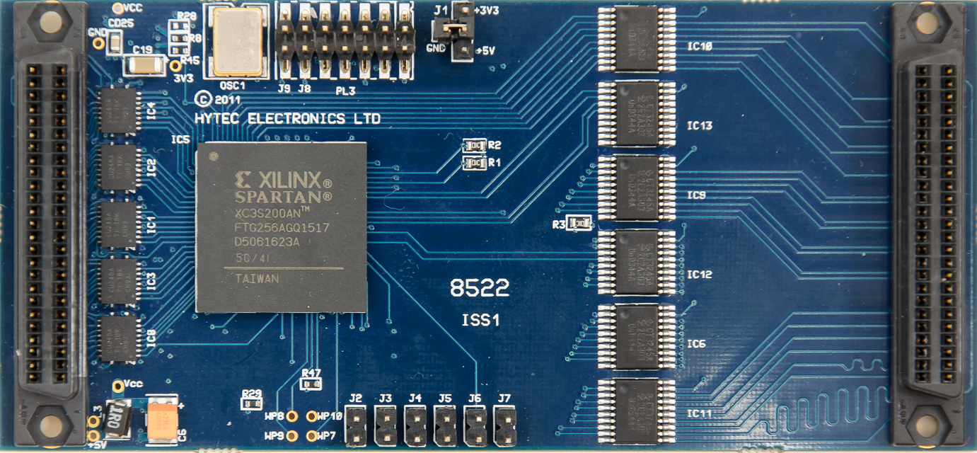
The IP-MSC-8522 is a single-width Industry Pack® that provides 16 scalers channels with the following characteristics:-
• 16 independent counting channels.
• 32-bit counter depth.
• Shadow register to allow on-the-fly reading of scalers.
• Full 32 bits binary count capacity and 64 bit histogram capability.
• 2Mbytes SRAM.
• Gate/Bin advance by internal timer or programmable number of external pulses.
• 200MHz Count rates (LVDS, LVPECL and NIM), 100MHz for TTL.
• TTL, LVDS and LVPECL inputs (Input type must be specified when ordered).
• Input type can be reconfigured in the field via the JTAG port if requirements change.
• NIM input via dedicated terminal block.
• Each scaler has a 16 bit input coincidence pattern register.
• Interrupt on completion of programmed number of cycles/triggers/counts.
• External hardware trigger (software enable) or software trigger.
• Trigger output to allow Trigger In / Out daisy-chain connection for synchronisation.
• Software and external hardware reset of scalers and memory.
• Scaler external inputs via transition board.
• Trigger ignored if cycle has not completed.
• Channel masking.
• Counter Overflow register.
• Number of Cycle/Triggers Received register.
• The ability to read the module identity, manufacturer, model, revisions, input type and serial number from an onboard ID ROM.
• In the field firmware upgrade capability.
Size: Single width Industry Pack 1.8ins x 3.9 ins.
Operating temp: 0 to 45 deg C ambient.
Number of channels: 16.
Max. count: 32 bits with IRQ at end of programmed number of cycles.
Data format: Binar.y
Count rate TTL: 0 to 100Mpps.
Count rate LVDS: 0 to 200Mpps.
Coincidence: 2ns min. overlap for detection.
Scaler Input levels: TTL compatible with positive or negative edge clocking or LVDS 3.3V.
Trigger/Reset levels: External Trigger Input. TTL compatible settable active low or active high options.
Trigger Delay: Maximum Trigger delay due to internal logic is 25ns.
Trigger Output levels: Trigger Output for synchronisation of modules. TTL compatible settable active low or active high options.
Clock accuracy: +/-50ppm (0.005%).
Power: +5V @ 250mA typical.
In this mode a histogram is formed for each channel. This is achieved by acquiring and logging the data for each channel over a number of programmable time intervals (gates/bins) for a programmable number of cycles.
• Gate/Bin advance by internal timer or programmable number external pulses (1 to 65525).
• Internal Gate intervals may be programmed from 100usec to 65secs
• Output pulse on each Gate/Bin advance.
• Programmable memory depth (number of time intervals or Gate/Bins) per triggered cycle of gate intervals up to 16k per channel of 64bit data.
• 64 bit totalisers records each channels total counts for each Gate/Bin.
• 64 bit totalisers records each channels total count for all Gates/Bins in each cycle.
• Dwell time approx 10us.
• Coincidence mode allows counting for coincidence on multiple inputs.
Straight scaler mode allows fixed or variable length counting time intervals. The interval length can be defined by an internal timer or by an external signal which can also be prescaled.
In this mode a time period or gate interval is set and when the unit is trigged the sixteen 32 bit counters will be enabled.
The gate interval can also be controlled externally by setting the EBA bit in the CSR. Here the timing pulses are user defined and received via the trigger input.
When the gate interval is finished the counter values are loaded in memory. The number of logged values is set in the Nos Cycles/Triggers register up to 32k per channel of 32bit data.
When the programmed number of triggers as set in the Number of Triggers register has occurred and the sequence completed, the Finished Flag (FF) in the CSR is set and an interrupt is generated if enabled.
• Gate/Bin advance by internal timer or programmable number external pulses (1 to 65525).
• Internal Gate (time) intervals may be programmed from 100usec to 65secs.
• Number of cycles register determines number of add-to-memory cycles up to 32K per channel 32bit counter data.
In this mode the counters are loaded with a preset count value. An arbitrary channel or a combination of channels can then be selected as the condition for the termination of the counting process for all counters. The selection of the channel(s) is done via the Count Termination Mask Register. The first selected channel that reaches its preset value will terminate the counting process and sets the FF flag in the CSR.
The individual counters can be driven from external inputs or from an internal pulse generator (selected by the Counter Source register). The internal pulse generator can be set to the following frequencies 25MHz, 50MHz, 100MHz or 200MHz.
Downloads